
 English
  русский
  Español
  Português

Industry News
Portal Frame Construction: Design, Spans, Components, and Steel Systems
Content
- 1 What Is a Portal Frame?
- 2 How a Portal Frame Carries Loads
- 3 Core Components of a Portal Frame Building
- 4 Main Types of Portal Frames
- 5 Typical Spans, Bay Spacing, and Proportions
- 6 Key Design Considerations Before Fabrication Starts
- 7 Portal Frame or Truss Frame: Which One Wins?
- 8 Construction and Erection: Step by Step
- 9 Common Applications of Portal Frame Construction
- 10 Portal Frame Construction: Frequently Asked Questions
- 10.1 What is the difference between a portal frame and a truss?
- 10.2 What is the maximum span of a steel portal frame?
- 10.3 Are portal frames cheaper than truss frames?
- 10.4 What does a moment connection mean in a portal frame?
- 10.5 How long does a steel portal frame last?
- 10.6 Can a portal frame be used for a bridge?
What Is a Portal Frame?
A portal frame is a rigid steel structural system in which vertical columns connect to horizontal or sloping rafters through moment-resisting joints. Because the column-to-rafter connection transfers bending moment instead of only vertical force, the frame resists wind, snow, crane, and roof loads without needing separate diagonal bracing.
The practical conclusion comes first: if you need a single-storey building with a wide, column-free floor area, a steel portal frame is normally the most economical structural system you can specify. This is why portal frames remain the dominant framing solution for warehouses, workshops, hangars, and agricultural buildings in virtually every market with an active steel construction sector.
The geometry is deceptively simple. Two columns and two rafters form one rigid bent. A row of bents, connected by purlins and side rails, makes up the primary and secondary structure of the building. The moment connection at the eaves is created with a haunch, a tapered deepening of the rafter section where it meets the column. The haunch spreads the peak bending moment over a longer steel length and prevents the connection from becoming a brittle point.
Site teams prefer the system because the details are familiar, the fabrication is straightforward, and the erection sequence is fast. Unlike a space frame or a complex lattice structure, a portal bent can be bolted together on the ground, checked for fit, and lifted as one piece. That simple fact is what keeps construction time short and quality control effective.
How a Portal Frame Carries Loads
The load path of a portal frame explains why it behaves as one continuous structure. Every load that arrives on the roof eventually travels down to the foundation through the same sequence:
- Roof sheeting and insulation transfer snow, rain, and maintenance loads to the purlins.
- Purlins span between rafters and pass the loads onto the rafter top flange.
- Rafters bend between the eave haunch and the apex, and the bending moment at the eaves grows with span.
- The moment connection at the top of the column passes that bending moment into the column.
- The column behaves like a vertical beam, bending over its height and transferring the load to the base.
- The base plate and anchor bolts deliver the forces into a reinforced concrete pad footing.
The two decisions that change the internal force distribution most are the base connection and the haunch geometry. A pinned base is designed to transfer axial force and shear only. It has a smaller base plate, fewer anchor bolts, and a smaller concrete footing, which is why it is the default for most frames between 12 m and 25 m span. A fixed base resists rotation at the column foot, which reduces the moment at the eave and can save steel in tall columns, but it costs more in foundations. The choice is an economic one, not a technical preference.
Horizontal loads such as wind, seismic action, and crane surge are resisted by frame action. Wind on the side wall bends the column, the moment passes through the haunch into the rafter, and the apex connection balances the opposing moments of the two rafter halves. The bent is stable in its own plane; stability perpendicular to the frame comes from roof plan bracing, side rails, and fly braces.
Core Components of a Portal Frame Building
Every portal frame, from a 12 m agricultural shed to a 45 m logistics hall, is assembled from the same set of parts. Understanding what each component does tells you where the engineering attention should go during design, fabrication, and site inspection.
| Component | Function | Typical Detail |
|---|---|---|
| Columns | Vertical member supporting rafter and transferring moment to the base | UB or UC sections; height 4 to 12 m |
| Rafters | Inclined roof member carrying purlin loads to the columns | Span 12 to 45 m; slope 5 to 10 degrees |
| Eaves haunch | Deepened section at the column-rafter junction, resisting peak bending moment | Depth about span/30 to span/40 |
| Apex haunch | Deepened section at the ridge, positive moment zone | Smaller than eave haunch; often cut from the same plate |
| Purlins | Span between rafters, supporting roof sheeting | Z or C sections; spacing 1.2 to 2.5 m |
| Side rails | Span between columns, supporting wall cladding | Z or C sections; spacing 1.2 to 2.0 m |
| Fly braces | Restrain the inner compression flange of the rafter | Angle sections near purlin lines |
| Roof and vertical bracing | Transfer longitudinal wind loads to foundations | Diagonal angles or flats in the end bays |
The eaves haunch deserves special attention during both design and fabrication. The maximum bending moment in a portal frame occurs exactly at the column-rafter junction, and at that location the bottom flange of the rafter is in compression. A correctly proportioned haunch deepens the section precisely where the stress is highest, raising the section modulus and saving steel over the rest of the span. Most problems in light portal frames start at this connection, either because the haunch is too short or because the compression flange was not restrained.
Main Types of Portal Frames
Portal frames are usually drawn as a single pitched bent, but the family includes several configurations, each selected according to span, use, and site constraints.
- Single-span portal frame - the classic choice for 12 to 30 m clear spans: one pitched roof, two columns, no internal columns, simplest details, and the lowest fabrication cost.
- Multi-span portal frame - several rigid frames placed side by side, sharing internal columns. This is the economical answer for wide floor plates where a line of internal columns is acceptable.
- Tapered portal frame - column sections and rafter depths taper toward the apex, saving weight on long spans and tall columns in exchange for more complex fabrication.
- Curved portal frame - the rafters follow a radius, giving a distinctive arched roofline for hangars, sports halls, and architectural statement buildings.
- Lean-to portal frame - a single-slope frame attached to a higher wall or an existing building, commonly used for extensions and covered walkways.
- Canopy portal frame - a shallower, often single-slope frame for loading bays, fuel stations, and covered parking with lighter loads and simpler base details.
- Truss portal frame - a portal frame whose rafter or column is replaced by a truss. It is used when spans pass roughly 40 m, or when heavy point loads from crane runways and suspended equipment must be carried.
For projects where the span goes beyond the practical limit of a rolled-section portal frame, or where heavy concentrated loads are involved, a truss frame is usually the better engineering answer. Modular steel bridges are the clearest example: the triangular lattice of the truss handles concentrated vehicle loads efficiently while keeping the structural depth reasonable.
Typical Spans, Bay Spacing, and Proportions
The cost of a portal frame is strongly influenced by span and bay spacing. The following ranges are what design teams use for early cost planning; they are planning ranges, not design tables.
| Building Type | Typical Clear Span | Typical Eave Height |
|---|---|---|
| Warehouse and logistics | 18 to 30 m | 6 to 8 m |
| Light industrial | 15 to 24 m | 5 to 8 m |
| Agricultural sheds | 12 to 24 m | 4 to 6 m |
| Sports halls and hangars | 25 to 45 m, often curved or trussed | 7 to 12 m |
| Retail and showroom | 12 to 20 m | 4 to 6 m |
As an early estimate, rafter depth is commonly in the range of span/40 to span/55 for rolled sections, and the eaves haunch depth is about span/30 to span/40. Column depth is typically one-third to half of the rafter depth plus the connection detail. Bay spacing usually falls between 5 m and 8 m: longer bays reduce the number of frames but force bigger purlins and heavier wind columns. Keep the same bay spacing for the full building, because changing it creates extra fabrication in the purlin runs.
For serviceability, the practical vertical deflection limit for cold-roof rafters is L/180 to L/240, while the horizontal drift at eaves is usually limited to H/150 to H/300. Crane buildings are stricter, at L/300 to L/600 depending on crane class. These deflection limits control the section size more often than pure strength, especially on long-span roofs where the self-weight of the steel is a large share of the total load.
Key Design Considerations Before Fabrication Starts
A portal frame project usually becomes expensive or difficult during decisions made before steel fabrication begins. These are the considerations that matter most.
- Load combinations. The design must consider dead load, imposed load, wind, snow, and where relevant crane and seismic actions, combined in the worst credible arrangement. On wide-span roofs, wind uplift often governs the design of purlins and base plates rather than downward load.
- Steel grade and corrosion protection. The usual structural grades are S235, S275, and S355. For exposed frames in coastal, chemical, or high-humidity environments, hot-dip galvanizing is the practical solution. A galvanized coating protects the steel for decades and removes the need for periodic repainting.
- Bracing and stability. The frame needs roof plan bracing in the end bays, vertical bracing between columns, fly braces to restrain the inner rafter flange, and enough robustness to handle a localised failure without collapse.
- Foundations. Pad footings, base plates, anchor bolts, and tie beams must be designed for the actual base reactions. A pinned base needs a modest footing; a fixed base needs a larger one. Increasing the base fixity to save steel rarely saves total project cost.
The single most common practical mistake in portal frame construction is forgetting to restrain the inner flange of the rafter near the haunch. That flange is in compression at the eaves region, and without a fly brace or similar restraint, the member can buckle sideways before it reaches its design moment. The fix is cheap; omitting it is not.
If you are evaluating steel members for a bridge or a long-span structure, our guide to steel beams for modular bridge construction explains member selection, span limits, and corrosion protection in practical terms.
Portal Frame or Truss Frame: Which One Wins?
The question is not which system is better in general, but which one fits the span, the load pattern, and the budget. The table below compares the two approaches across the criteria that drive real project decisions.
| Criterion | Portal Frame | Truss Frame |
|---|---|---|
| Connections | Moment-resisting eaves joints | Mostly pinned triangular joints |
| Primary material behavior | Bending in columns and rafters | Axial tension and compression in members |
| Economical span range | 12 to 45 m | 30 to 80 m or more |
| Best load type | Uniform roof loads | Point loads, moving loads, long spans |
| Fabrication cost | Low, because joints are simple and repetitive | Higher, because of many members and gussets |
| Erection speed | Fast, with few pieces per bent | Slower, with more pieces to align |
A regular 18 to 30 m warehouse with a light roof should almost always be a portal frame. A 50 m covered hall carrying a heavy crane, or a highway bridge deck carrying vehicle loads, should almost always be a truss. The reason is material efficiency: in a truss, members carry loads axially, so the full cross-section works, while a bending member has a large part of its material stressed well below its capacity.
When the project is a temporary bridge, a long-span access route, or a heavy-load crossing, a truss-type modular system gives predictable capacity and fast deployment. The large-span heavy-load galvanized Bailey bridge is a typical example of a truss structure built for that exact duty.
 Wholesale CB450 Type Large Span Heavy Load Galvanized Bailey Bridge ManufacturerJiangsu Zhonghai Bridge Equipment Co., Ltd. is a China CB450 Type Large Span Heavy Load Galvanized Bailey Bridge manufacturers and OEM fa...View Product →
Construction and Erection: Step by Step
The erection sequence affects cost, programme, and site safety more than any other activity. A well-planned sequence follows these steps in order.
- Foundations. Cast pad footings with anchor bolt cages set to the base plate geometry. Verify bolt positions before the concrete hardens.
- Ground assembly. Lay out columns, rafters, and haunches on the ground, and bolt the two rafter halves and the haunch into a single bent where possible.
- Column erection. Lift each column onto the anchor bolts and hold it with temporary guys before the rafter is placed.
- Frame lifting. For a small frame, the complete bent is lifted and bolted. For large spans, lift each column and rafter half separately and make the apex connection in the air.
- Tightening. High-strength bolted connections are tightened in sequence from the stiffest point outwards. Slip-critical joints are marked and checked after tightening.
- Secondary steel. Install purlins and side rails, using them to align adjacent frames before the cladding goes on.
- Bracing. Install roof plan bracing and vertical bracing before releasing the crane. The structure is not stable until these are complete.
- Cladding. Fix roof sheeting, insulation, wall panels, and flashings in a sequence that keeps the interior weathertight as early as possible.
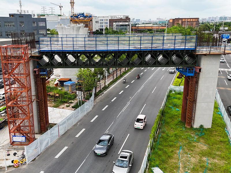
During steps 3 to 5, temporary support is critical. A portal frame becomes self-supporting only after the first complete bent and its bracing are in place. On projects where the frame spans are long, or where the crane must be released quickly, a temporary stiffened support is the standard solution. The 900-ton rated super Bailey construction support used on large-span bridge and railway works is a practical example of this type of temporary steelwork.
 Wholesale Customized Large Span 900 Ton Load Super Bailey Construction Support MJiangsu Zhonghai Bridge Equipment Co., Ltd. is a China Customized Large Span 900 Ton Load Super Bailey Construction Support manufacturers...View Product →
Quality control on site is mostly visual: check bolt protrusions, confirm that fly braces are fitted at every purlin line near the haunch, verify that the bracing is tensioned, and never allow cladding to be fixed before the bracing is signed off.
Common Applications of Portal Frame Construction
The strength of a portal frame is clear, unobstructed space. That single advantage explains its spread across a wide range of building types.
- Warehouses and distribution centres with racking layouts that need column-free floors.
- Manufacturing workshops and factories where cranes, presses, and assembly lines dictate the roof structure.
- Agricultural buildings for livestock, machinery, grain storage, and covered feeding areas.
- Aircraft hangars and sports halls, where the clear span is the entire point of the building.
- Retail units, showrooms, and service buildings that need to be erected in weeks, not months.
- Canopies and loading bays attached to larger buildings, often built as lean-to or canopy frames.
- Industrial process buildings with crane runways and heavy roof-mounted plant.
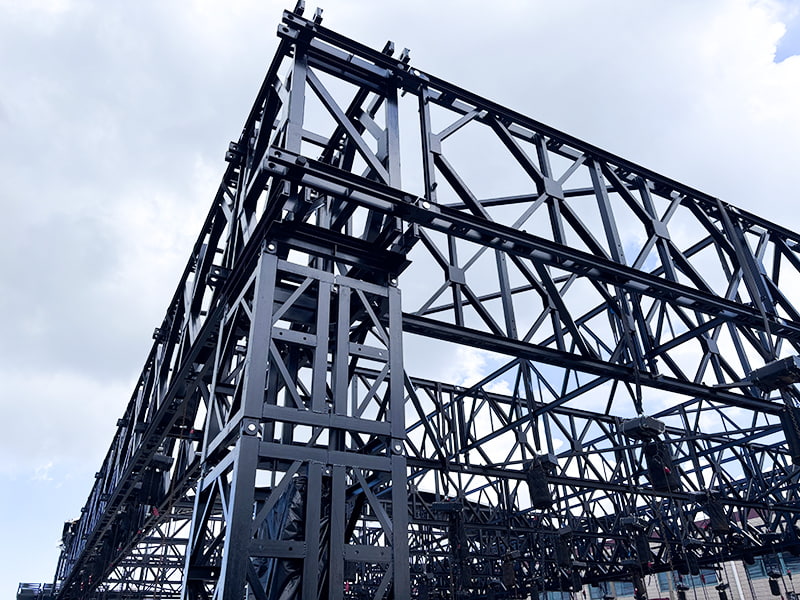
The same engineering principles, rigid connections, steel sections, and corrosion protection also apply outside buildings. Our modular steel structure systems cover bridge approach structures, pipe supports, and temporary platforms, extending the portal frame logic into infrastructure work.
 Custom Steel Structure Manufacturers, Steel Structure System FactoryAs China steel structure manufacturers and steel structure system OEM factory, Zhonghai Bridge Equipment Co., Ltd specialize in custom an...View Product →
In bridge and infrastructure projects, portal-type frames appear as temporary access structures, erection gantries, and cross-bridge construction platforms. The load path and stability logic are identical to a building frame, but the loads are heavier and the tolerances tighter. A well-planned set of bridge construction platform applications can turn a risky over-water installation into a routine lifting sequence.
Portal Frame Construction: Frequently Asked Questions
What is the difference between a portal frame and a truss?
A portal frame uses rigid joints between columns and rafters so that bending moment is carried through the connection. A truss uses triangulated members with pinned connections, and the members carry mostly axial forces. Portal frames are normally cheaper up to roughly 40 m span; trusses take over for longer spans, heavy point loads, and bridge applications.
What is the maximum span of a steel portal frame?
Rolled-section portal frames rarely go beyond 45 to 50 m before the rafter weight becomes excessive. Beyond that range, designers switch to truss rafters, cellular beams, or an internal line of columns if the building use allows it. The practical maximum single-span steel portal frame in common practice is around 60 m using a truss-type rafter.
Are portal frames cheaper than truss frames?
For spans under 30 m, usually yes. A portal frame has fewer pieces, less welding, simpler connections, and faster erection. Above 45 m or with heavy crane loads, the truss often becomes cheaper because its members carry load axially, which reduces member sizes significantly and offsets the extra fabrication cost.
What does a moment connection mean in a portal frame?
A moment connection transfers bending moment as well as axial and shear forces. In a portal frame, the eaves connection is a moment connection, which is why rafter loads can be carried down to the column without a separate brace. Without moment capacity at the joint, the frame would be a mechanism and would need diagonal bracing to remain stable.
How long does a steel portal frame last?
That depends mainly on corrosion protection, not on the steel itself. A well-detailed portal frame with hot-dip galvanizing or a durable paint system easily lasts 50 years or more in typical atmospheric conditions. The roof cladding will normally need replacement earlier than the frame; the frame lifetime is governed by coating maintenance and condensation control.
Can a portal frame be used for a bridge?
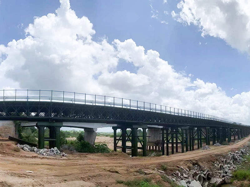
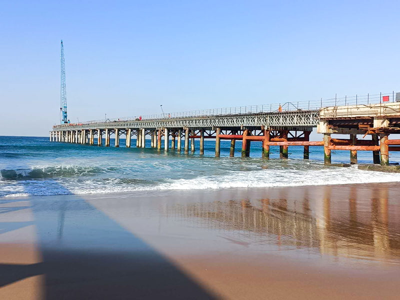
Building-style portal frames are sometimes used for short rigid-frame bridges, but for most bridge ranges a truss-type modular system is more practical. You get better use of material, a shallower structure, and predictable capacity from prefabricated panels. The most common way to build temporary or permanent steel bridges quickly is with a modular truss system such as a Bailey bridge; the Bailey bridge load capacity and specification guide explains the load classes and configurations used in practice.

We respond quickly to all international requests and provide technical support when needed.
Product Category
Bailey Bridge/Modular Bridge Modular Steel Bridge Pedestrian Bridge Modular Pipe Bridge Truss Bridge Steel StructureContact Us

+86-511-84522866
+86-13921582699

zhwm@zjql.com

Building 1,83#, dantu New Town, Yanjiang Road, Dantu District, Zhenjiang, Jiangsu, China
Copyright © Jiangsu Zhonghai Bridge Equipment Co., Ltd. All
Rights
Reserved
China bailey bridge for sale
bailey bridge supplier from china
