
 English
  русский
  Español
  Português

Industry News
Steel Structure Installation Guide: Step-by-Step Erection Process for Modular Bridges
Content
- 1 Steel Structure Installation: What the Complete Process Really Involves
- 2 Site Preparation and Foundation Tolerances
- 3 Receiving, Inspection, and Pre-Assembly Before the Crane Arrives
- 4 Choosing the Erection Method: Crane Lifting, Launching, or Gantry
- 5 Step-by-Step Assembly Sequence for Modular Steel Bridges
- 6 Connection Control: Bolts, Pins, and Site Welds
- 7 Safety Rules and the Most Common Installation Mistakes
- 8 Frequently Asked Questions About Steel Structure Installation
- 8.1 How long does it take to install a modular steel bridge?
- 8.2 Can a modular steel bridge be installed without a crane?
- 8.3 What is the most common installation error?
- 8.4 Why are anchor bolts so critical in steel structure installation?
- 8.5 When is a launching nose required?
- 8.6 How should the final inspection be organized?
Steel Structure Installation: What the Complete Process Really Involves
A steel structure works only when the installation makes every member carry its share of the load. The steel itself is usually not the weak point; connection quality, erection sequence, and foundation accuracy determine whether the finished bridge or building performs as designed. This guide explains the complete steel structure installation process for modular steel bridges and prefabricated steel buildings, from foundation preparation through to final inspection.
The direct answer is this: prepare the foundation inside tolerance, inspect every component before lifting, pre-assemble what you can on the ground, erect the primary frame in a fixed sequence, tighten every connection to the drawing value, and only then install decking, cladding, and finishes. Skipping one stage makes the next stage slower, more expensive, or unsafe.
- Foundation readiness sets the fastest realistic erection speed.
- Ground pre-assembly reduces crane time and exposes fit-up problems early.
- Connection control, not member strength, decides the final safety of the structure.
- For modular bridges, the choice between crane lifting and launching depends on span, weight, and site access.
| Stage | Core activity | Critical check |
|---|---|---|
| Foundation preparation | Anchor bolt setting, plinth casting, survey | Bolt positions, top elevation |
| Component inspection | Offloading, counting, damage check | Quantities against packing list, coating condition |
| Pre-assembly | Sub-frame fit-up on the ground | Hole alignment, diagonal dimensions |
| Primary erection | Columns, panels, beams placed and bolted | Plumb, level, temporary bracing |
| Connections | Bolts torqued, pins driven, welds inspected | Torque values, pin seating, weld size |
| Deck and finishing | Deck units, handrails, cladding, touch-up | Final alignment, coating repair |
Site Preparation and Foundation Tolerances
The installation crew's most valuable information is not the erection drawing; it is the as-built survey of the foundation. For a modular steel bridge, the abutment seats and bearing elevations must be inside tolerance before the first panel is lifted. For a steel building, the anchor bolt pattern must match the column base plates. Most delayed projects are not delayed by steel fabrication errors; they are delayed by anchor bolts cast more than a few millimeters away from the theoretical position.
Typical field tolerances for steel structure foundations include:
- Anchor bolt group position: +/-3 mm from the theoretical center of the group.
- Top of concrete elevation at bearing areas: +/-5 mm.
- Anchor bolt projection above concrete: typically +20 mm / -0 mm so that nuts and washers seat fully.
- Beam seats and corbels: horizontal within 1:500 and level within +/-3 mm.
Concrete has a strength condition as well. Erection loads should not be applied before the concrete has reached roughly 75 percent of its design strength, as stated on the structural drawings. Loading a foundation too early is one of the few erection errors that cannot be fully corrected later.
Before mobilization, check the ground conditions for crane outriggers and the horizontal distance from the crane pivot to the far edge of the span. A small change in crane radius can reduce the available lift capacity significantly, so the crane position should be marked and verified before the first lift.
Receiving, Inspection, and Pre-Assembly Before the Crane Arrives
Steel components arrive as a kit. Between the factory and the site they can be bent during offloading, scratched by chain slings, or mixed with components from another delivery. Receiving inspection is therefore a schedule-protection step, not paperwork. The receiving check should follow this order:
- Offload each member at the marked lifting points with slings of adequate rating; never drag panels or beams over gravel or concrete.
- Match the packing list against the actual components before the transport leaves the site, and note missing or damaged items on the delivery receipt.
- Measure diagonals on truss panels and check beam ends for squareness; a distortion of a few millimeters becomes a difficult fit-up later.
- Inspect threads on bolts and anchor rods, and replace or repair damaged threads before erection.
- Separate bolt, pin, and washer lots by grade and size, and store them under cover.
Pre-assembly on the ground is the cheapest quality check in steel construction. For a bailey-type modular bridge, the crew assembles side panels, transoms, and bracing into complete bays on level ground, verifies hole alignment and diagonal dimensions, and only then lifts or launches the bay. For steel buildings, columns and rafters are often bolted into frames on the ground and raised as one piece. This reduces the number of crane lifts and keeps the frame geometry accurate.
Choosing the Erection Method: Crane Lifting, Launching, or Gantry
The erection method is selected from the span, the component weight, and what the site allows. There is no best method in general; there is only the method that matches the site.
| Method | Typical application | Main equipment | Key control |
|---|---|---|---|
| Crane erection | Short spans, buildings, accessible banks | Mobile or truck crane | Crane radius and lift capacity |
| Cantilever launching | Long spans over rivers, valleys, live traffic | Launching nose, rollers, winch | Nose deflection, roller positions |
| Gantry erection | Heavy segments above a completed span | Overhead gantry or launching girder | Rail alignment, segment balance |
| Barge crane | Water crossings with deep channels | Floating crane with barge | Water level, current, anchorage |
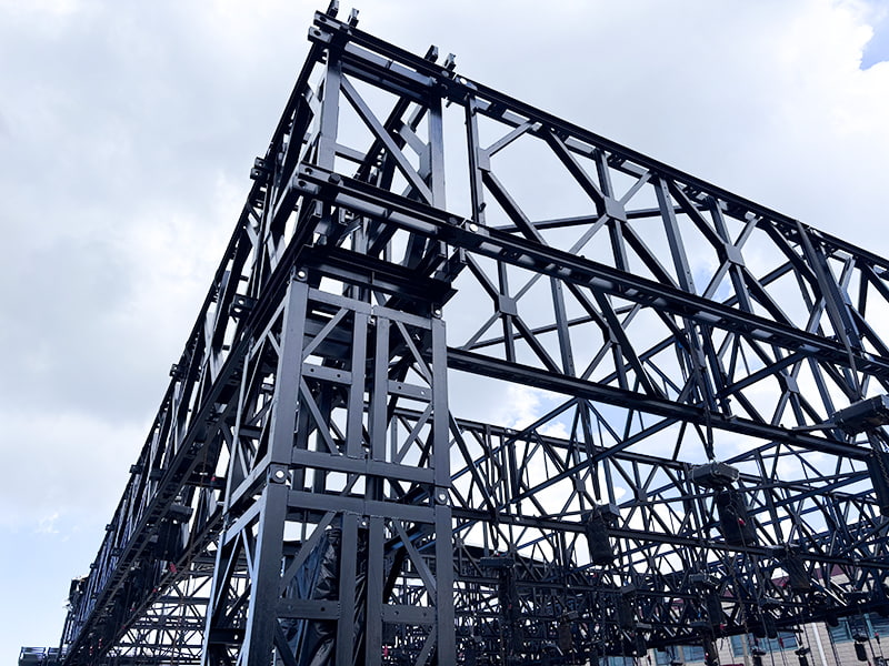
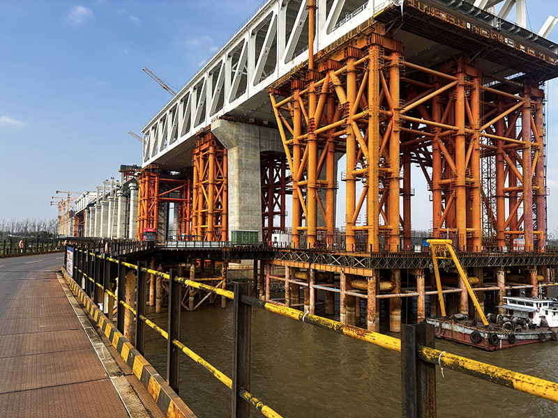
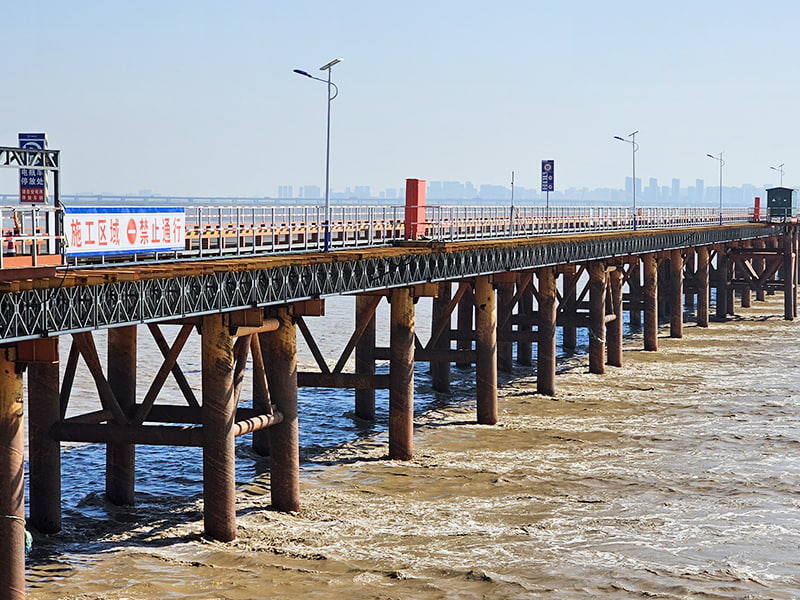
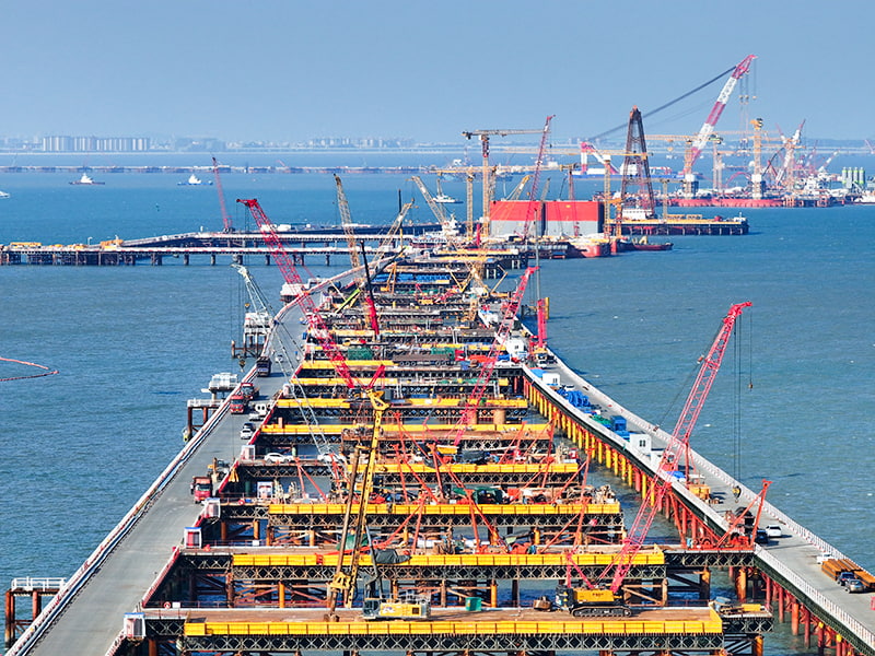
Every method shares one rule: the structure must be stable at every intermediate step, not only in the final state. Temporary bracing and temporary supports are part of the installation design, not field improvisation. On bridge sites where crews need a stable working surface under the span, large-span heavy-load construction platforms provide an engineered alternative to scaffolding and allow erection work to continue above water or live traffic.
 Wholesale Large Span Heavy Load Construction Platforms for Bridges ManufacturersJiangsu Zhonghai Bridge Equipment Co., Ltd. is a China Large Span Heavy Load Construction Platforms for Bridges manufacturers and OEM fac...View Product →
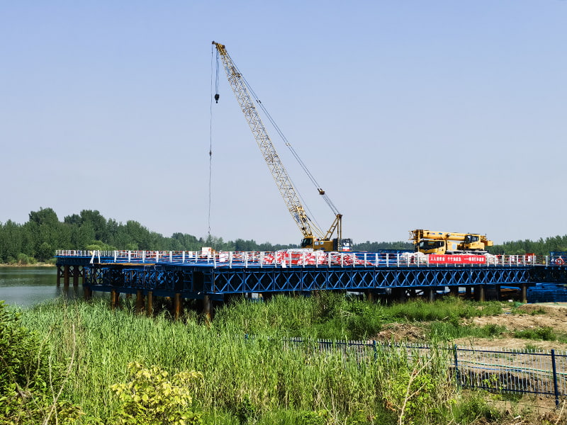
For modular steel bridges, the usual decision is between crane erection and launching. Crane erection is faster when the total bridge weight is inside the crane chart at the required radius and the ground supports the outriggers. Launching is used when the crossing is too long, too deep, or too busy for a crane. The bridge is assembled on rollers behind the near abutment, a lightweight launching nose is attached to the front, and a winch pulls the whole structure forward until the nose lands on the far bank. Rollers must sit at panel node points so the concentrated reaction does not dent the chord. The connection and load-path principles behind this method are covered in the modular steel bridge construction guide.
Step-by-Step Assembly Sequence for Modular Steel Bridges
Once the erection method is fixed, the field sequence follows a repeatable pattern. A typical single-span bailey-type installation with launching works through these steps:
- Set the end posts and bearing plates on the abutment seats; check the bearing level and line.
- Assemble the first bays on the launching side, connecting side panels with transoms and inserting panel pins.
- Install sway braces and cross bracing as each bay is completed so the bay stays square.
- Fit stringers and deck units after the bay framing is pinned; the deck also stiffens the bay.
- Advance the bridge with a winch or excavator, keeping the launching nose pointed at the far bearing.
- When the main girder reaches the far seat, lower the structure onto the bearings and remove the launching equipment.
- Install handrails, approach plates, and expansion joints.
- Run a final alignment survey, repair coating damage, and hand over the structure.
Modular panel systems differ mainly in capacity and configuration. The CB-200 bailey bridge is a reinforced multi-row system for longer spans and heavier loads, so its installation uses more cross-bracing and a heavier launching nose, but the working sequence is the same. High-capacity systems need extra care during launching because the assembled weight per linear meter is higher.
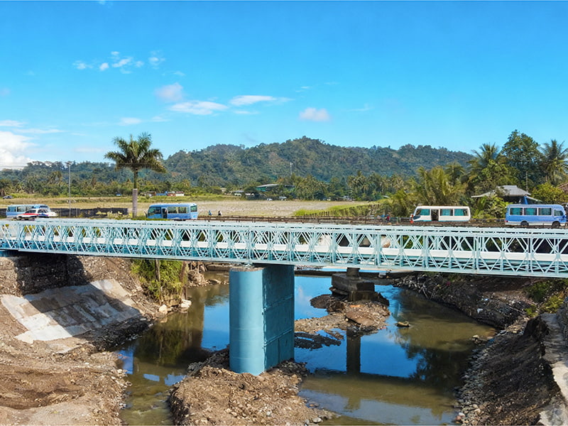 Custom CB 200 Bailey Bridge Supplier, OEM CB 200 Bailey Bridge FactoryAs China cb 200 bailey bridge supplier and cb 200 bailey bridge OEM Factory, Zhonghai Bridge Equipment Co., Ltd specialize in custom and ...View Product →
Before choosing a panel configuration, check the Bailey bridge specifications and load capacity guide to match the girder arrangement to the required span and load. Choosing a stronger configuration than needed does not improve safety; it only adds weight that the launching equipment must handle.
Connection Control: Bolts, Pins, and Site Welds
Most field problems in steel structures start at connections, not in the members. A bolt left at snug condition, a pin that is not fully seated, or a site weld with undercut will eventually become a cracking point. Connection control is the heart of steel structure installation.
Bolted connections
High-strength bolts in structural connections are installed in two passes. The first pass brings the joint to snug-tight condition, meaning the connected parts are in firm contact. The second pass applies the final torque with a calibrated torque wrench set to the value on the drawing. Bolts should not be reused for critical connections because torque-tension behavior changes after the first tightening.
| Bolt size and grade | Typical final torque (Nm) |
|---|---|
| M16 - class 8.8 | 190 to 220 |
| M20 - class 8.8 | 380 to 480 |
| M22 - class 8.8 | 510 to 640 |
| M24 - class 8.8 | 660 to 830 |
Pinned connections
Modular bridges use panel pins at the main panel joints instead of bolts. A correctly installed pin is fully driven, seats flush with the chord face, and is secured with its retaining clip. A partially driven pin is dangerous: the load concentrates on a small area of the pin hole, which elongates the hole and weakens the panel.
Site welding
Where site welding is allowed for splices, bracing, or repairs, inspect the welds visually for cracks, undercut, and porosity before the final coating. Fillet weld leg size should be checked with a weld gauge against the drawing. Coating comes after inspection, not before, because paint hides weld defects.
Safety Rules and the Most Common Installation Mistakes
Erection is the highest-risk phase of any steel project because crews work at height, with heavy loads, and under time pressure. The controls that matter most are simple and repeatable.
Safety rules that must not be relaxed
- Confirm the crane capacity at the actual radius before each lift; a chart value at a small radius does not apply to the far side of the span.
- Stop lifting when wind speed exceeds the crane manufacturer's limit, typically 10 to 14 m/s depending on the machine and the lifted surface area.
- Keep everyone clear of suspended loads and use tag lines to control rotation.
- Install temporary bracing in the same shift as the frame erection; an unbraced steel frame left overnight is a common cause of collapse.
- Inspect slings, shackles, and spreader beams daily, and retire any damaged gear.
Common mistakes to avoid
- Lifting a frame before the base plate bolts are set; the structure shifts during the lift and alignment is lost.
- Tightening bolts in a later shift without marking the snug-tight pass; skipped bolts remain hidden in the final torque check.
- Hammering a pin that does not align with its hole. The misalignment, not the pin, is the problem; recheck the bay before forcing the connection.
- Repairing damaged galvanized coating with ordinary paint. Use a zinc-rich repair compound so the corrosion protection matches the original.
- Treating temporary supports as a field improvisation. Temporary structures carry real loads and need a design basis; engineered options such as the customized large-span super bailey construction support
 Wholesale Customized Large Span Super Bailey Construction Support Manufacturers,Jiangsu Zhonghai Bridge Equipment Co., Ltd. is a China Customized Large Span Super Bailey Construction Support manufacturers and OEM fact...View Product → are far safer than improvised cribbing.
The same logic applies to access. On bridge projects, contractors often underestimate how much time the crew spends working over water or traffic. A properly designed working platform shortens the critical path and reduces fall risk; the bridge construction platform applications article shows where these platforms are typically used.
Frequently Asked Questions About Steel Structure Installation
How long does it take to install a modular steel bridge?
A single-span bailey-type bridge of 20 to 30 m can normally be installed in three to seven days with a crew of six to ten workers and one crane, assuming the foundation is ready and all components are on site. Launched installations over long spans typically take one to three weeks. In most cases, site preparation and inspections control the schedule more than the assembly work itself.
Can a modular steel bridge be installed without a crane?
Yes. Bailey-type modular bridges are designed for launching, so a full installation can be done with rollers, a winch, and a pulling excavator. The launching nose controls the cantilever moment during the push. Very heavy high-capacity configurations may still need a crane for the first bay or for final adjustments on the far bearing.
What is the most common installation error?
In modular bridge work, it is misalignment between a panel pin and its hole, followed by hammering the pin to force the joint. In general steel building work, it is undertorqued high-strength bolts. Both errors produce hidden damage that appears later under load.
Why are anchor bolts so critical in steel structure installation?
The anchor bolt pattern fixes the position of every column or bearing. If the foundation survey shows bolt positions outside the +/-3 mm tolerance, the steel cannot be installed to the drawing without modification. Checking anchor bolts before concrete placement is far cheaper than correcting them after.
When is a launching nose required?
A launching nose is required whenever a bridge is pushed across a span, because the cantilever moment of the incomplete structure must be controlled. The nose is typically around 60 percent of the span length for a single-span bailey bridge, although the exact length comes from the erection calculation for each project.
How should the final inspection be organized?
Walk the line of the structure systematically: check bearing seating, pin retaining clips, bolt torque marks, weld sizes, coating repairs, and deck joints against a printed checklist. A clean, well-documented inspection is the fastest possible handover.
Steel structure installation is deterministic. If every component is the right one, every connection reaches the specified torque or pin seating, and the erection sequence is respected, the finished structure behaves exactly as the design intended. The companies that deliver trouble-free installations are not the ones with the fastest crane; they are the ones with the most disciplined site process.

We respond quickly to all international requests and provide technical support when needed.
Product Category
Bailey Bridge/Modular Bridge Modular Steel Bridge Pedestrian Bridge Modular Pipe Bridge Truss Bridge Steel StructureContact Us

+86-511-84522866
+86-13921582699

zhwm@zjql.com

Building 1,83#, dantu New Town, Yanjiang Road, Dantu District, Zhenjiang, Jiangsu, China
Copyright © Jiangsu Zhonghai Bridge Equipment Co., Ltd. All
Rights
Reserved
China bailey bridge for sale
bailey bridge supplier from china
